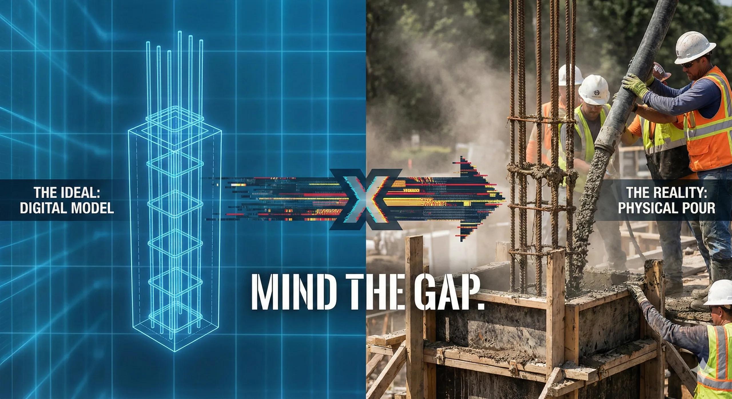
Most construction delays don’t start on the site, they start in the digital models long before anyone arrives with concrete, steel, or surveying equipment. Errors propagate quietly through design files, outdated PDFs, uncoordinated revisions, or misaligned coordinate systems. When field teams receive this information weeks later, the damage is already done.
This is the core reason BIM-to-field workflows fail : design intent and field reality never stay in sync.
Construction is inherently spatial. Every element, be it a footing, a duct, a beam, or a prefabricated wall, must exist at a precise location with a precise dimension. When data is fragmented across BIM platforms, GIS systems, drone surveys, and spreadsheets, spatial truth becomes inconsistent. And when spatial truth becomes inconsistent, workflow reliability collapses.
This article explains the root causes behind failed BIM-to-field processes and outlines a data-integrated approach for a more accurate, efficient, and resilient construction lifecycle.
1. The Root Misalignment: BIM Geometry vs Field Geometry
Even in well-managed projects, three types of misalignment emerge.
A. Geometric Misalignment
These errors start small but produce large downstream impacts:
Misconfigured project coordinate systems
BIM models built without geospatial references
Incorrect survey benchmarks
Improperly registered point clouds
A misalignment of even 10–20 mm can:
Push anchor bolts off-centre
Cause MEP connections to miss
Create cumulative errors in prefabricated assemblies
The field then “corrects” the perceived mistake, but the model remains unchanged, creating an endless loop of discrepancy.
B. Semantic Misalignment
A model may look complete but lack metadata accuracy. Common issues:
Missing or inconsistent parameters
Incorrect element naming
Undefined classifications (COBie, Uniclass)
Poor family standards
Field teams rely on metadata for:
Installation instructions
Material specifications
Quantity take-offs
Asset tagging
When semantics fail, field interpretation becomes guesswork.
C. Temporal Misalignment
Construction never pauses, but models do.
By the time updates reach the field:
RFIs remain unresolved
Coordination changes aren’t published
As-built updates lag behind reality
Schedules and 4D linkages are outdated
A field team working with a 3-week-old model is essentially working blind.
2. Why BIM-to-Field Workflows Break in Practice
Even with advanced platforms like Autodesk Construction Cloud, Trimble Connect, Navisworks, or SYNCHRO, the failure persists for structural reasons.
Problem 1: BIM is Not Natively Geospatial
Most BIM tools were designed for design , not real-world spatial accuracy . This creates:
CRS mismatches
Difficulties in overlaying with drone or LiDAR data
Misalignment with GNSS-based surveying
Problem 2: Geospatial Tools Don’t Speak BIM Natively
GIS systems produce:
GeoTIFF
LAS/LAZ
GPKG
Shapefiles
BIM tools cannot directly interpret these formats without intermediate steps.
Problem 3: Too Many Systems, Too Little Integration
Projects commonly use:
BIM for design
GIS for site understanding
Drone surveys for as-built evidence
Spreadsheets for quantities
Scheduling tools for 4D
Mobile apps for field inspections
IoT dashboards for operations
This leads to parallel truths , not a single source of truth.
Problem 4: Field Teams Still Rely on Static Documents
Even with digital tools available, field workflows often end with:
PDFs
Static drawings
Screenshots
WhatsApp images
Email-based clarifications
These fragments fail to represent the dynamic nature of construction.
3. Building an Integrated Data Workflow
A robust BIM-to-field workflow requires five integrated layers .
Layer 1: Geospatial Referencing
A unified coordinate system for:
BIM models
Drone imagery
LiDAR scans
Survey points
This allows:
Accurate overlays
Seamless deviation analysis
Reliable layout and machine guidance
Layer 2: Reality Capture Integration
Regular drone flights, LiDAR scans, and terrestrial scans provide:
Orthomosaics
Dense point clouds
3D meshes
They capture what is actually happening , allowing comparison with design.
Layer 3: Design Model Synchronization
Design must remain tightly coordinated:
IFC exchanges
Version-controlled models
Linked schedules (4D)
Cost integrations (5D)
Layer 4: Field Execution Tools
Site teams need:
Tablets with BIM viewers
AR overlays
QR/RFID asset tagging
Digital checklists
Connected issue tracking
This closes the loop between model and execution.
Layer 5: Operational Integration
Once the asset is live:
Sensors communicate with BIM
Digital twins track degradation
Predictive maintenance becomes possible
The BIM model evolves from design documentation into an operational intelligence layer .
4. What Integrated Data Fixes
A. Eliminates Guessing in the Field
Surveying, layout, and installation become data-driven.
B. Reduces Rework and Cost Overruns
Deviations are caught early, sometimes instantly.
C. Improves Coordination and Timeline Reliability
4D and 5D models reflect real conditions, making planning accurate.
D. Enables Automated Digital Twins
The as-built model updates continuously rather than through manual rework.
Conclusion
BIM-to-field workflows fail not due to tool limitations, but because the data ecosystem is fragmented .
The solution is integrated data, geospatially anchored, continuously updated, semantically consistent, and operationally connected.
When integration becomes the foundation, construction transforms:
Rework drops
Schedules stabilize
Field teams operate confidently
Digital twins emerge naturally
Decision-making becomes analytical instead of reactive
This is the future of the AECO industry: design and reality moving together, not apart.