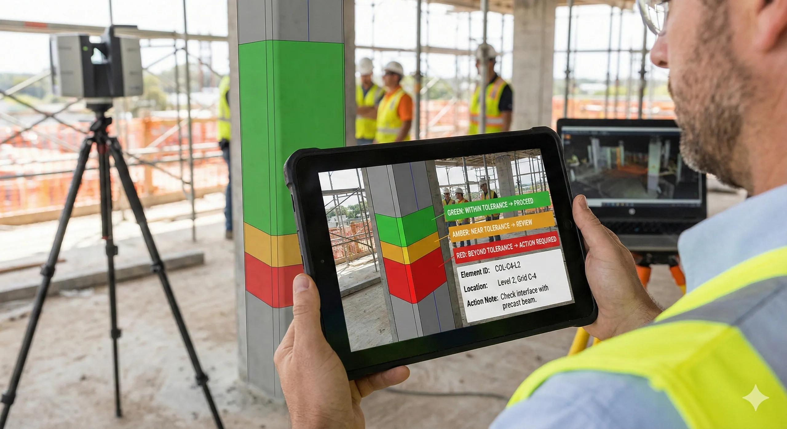
Tolerance checking is often presented as a visual exercise, heat maps, color gradients, and screenshots showing where reality deviates from design. But in practice, tolerance checking is not a visualization task . It is a decision framework that determines whether construction can proceed, whether rework is required, or whether a deviation is acceptable.
When tolerance checking is poorly defined, teams argue over colors. When it is well defined, teams make decisions.
This article explains how to compare point clouds to BIM models in a way that produces actionable tolerance intelligence , not just visual artifacts.
1. Why Tolerance Checking Commonly Fails
Most tolerance workflows fail due to:
No agreed tolerance thresholds
Comparing entire models instead of relevant elements
Mixing progress checks with QA checks
Using visuals without quantitative backing
As a result:
Heat maps look impressive
Meetings go long
Decisions get postponed
Tolerance checking must be rule-driven , not screenshot-driven.
2. Tolerance Is Contextual, Not Absolute
A critical misconception:
There is one tolerance value for the whole project.
In reality:
Structural elements have different tolerances than finishes
MEP systems have tighter interface tolerances
Temporary works often have no tolerance requirement
Tolerance must be defined by:
Element type
Construction phase
Downstream risk
Without context, tolerance checking produces noise.
3. The Prerequisites for Reliable Tolerance Checking
Before any comparison begins, ensure:
✔ Accurate scan registration
✔ Correct georeferencing
✔ Matching coordinate systems
✔ Verified vertical datum
✔ Classified point clouds
Skipping any of these invalidates results.
4. What Should Be Compared (And What Shouldn’t)
Compare:
Columns vs column models
Slabs vs slab surfaces
Beams vs beam geometry
MEP runs vs modeled systems
Do Not Compare:
Entire point cloud vs entire BIM
Temporary works vs permanent models
Construction clutter vs design geometry
Precision comes from selective comparison .
5. Distance-Based vs Surface-Based Checks
Distance-Based Checks
Measure point-to-model distance
Useful for spot validation
Sensitive to noise
Surface-Based Checks
Compare surfaces or regions
Better for slabs, walls, facades
More stable results
Choose the method based on geometry and decision need.
6. Defining Tolerance Bands That Matter
Instead of continuous gradients, use decision bands :
Green: within tolerance → proceed
Amber: near tolerance → review
Red: beyond tolerance → action required
These bands must be agreed before analysis.
7. Progress vs Quality: Do Not Mix Them
A common mistake is using tolerance tools to infer progress.
Progress asks: Is it built?
Tolerance asks: Is it built correctly?
Mixing them leads to false conclusions.
8. Reporting Tolerance in a Field-Usable Way
Field teams need:
Clear pass/fail zones
Element IDs
Location references
Action notes
They do not need:
Dense color maps
Full point cloud files
Long explanations
Tolerance outputs must support execution , not analysis theatre.
9. Tolerance Checking in the Indian Context
On Indian sites:
Design evolves during construction
Execution variability is higher
Documentation gaps are common
Tolerance checking works best when:
Used early to prevent compounding errors
Focused on interfaces
Framed as risk mitigation, not fault finding
10. A Simple Rule for Tolerance Checking
Before running any comparison, ask:
What decision will this tolerance result trigger?
If the answer is unclear, the check is premature.
Conclusion
Tolerance checking is not about proving deviations, it is about protecting downstream decisions .
When done correctly:
Rework is avoided
Interfaces are controlled
Trust in BIM increases
Reality capture earns its place
When done poorly:
Heat maps replace decisions
Teams argue over colors
Digital workflows lose credibility
In BIM-to-field execution, tolerance checking succeeds only when it is designed to answer a specific question, not to impress a screen .