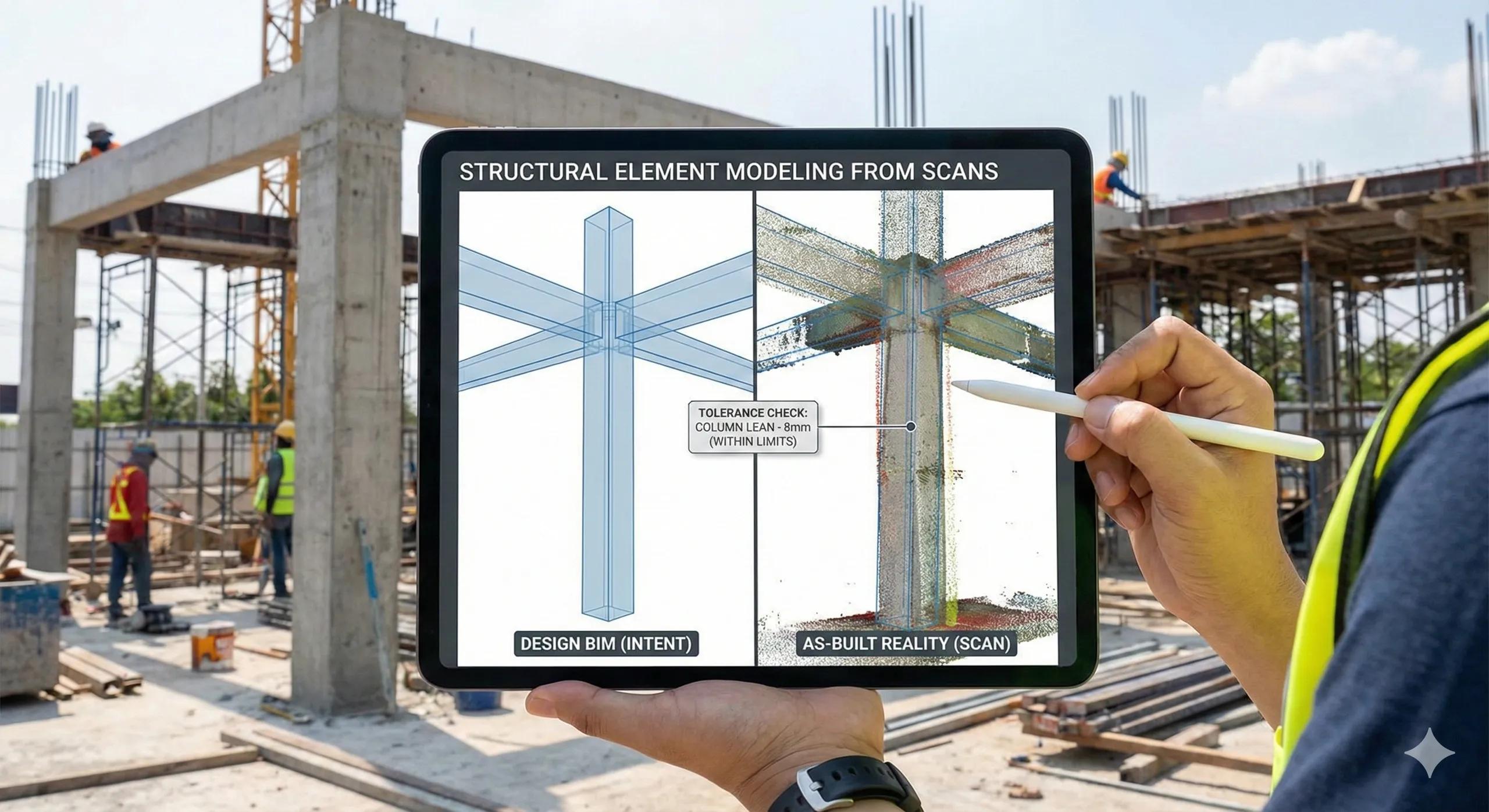
Structural elements are often the first candidates for Scan-to-BIM, and also the fastest place for things to go wrong. Columns get over-fitted, slabs get over-smoothed, beams get modeled with false precision, and suddenly the BIM no longer reflects construction reality.
Structural Scan-to-BIM only works when modeling intent, tolerance, and usage are clearly defined upfront . Otherwise, teams end up spending time creating “perfect” geometry that does not support sequencing, QA, or downstream trades.
This article explains how to model structural elements from scans responsibly , when modeling adds value, and where restraint matters most.
1. Why Structural Scan-to-BIM Is Different from Design BIM
Design BIM represents idealized intent :
Perfect verticality
Clean intersections
Nominal dimensions
As-built reality captures:
Construction tolerances
Minor misalignments
Surface irregularities
Execution variability
Scan-to-BIM must bridge this gap without pretending reality is perfect .
2. Decide First: Why Are You Modeling This Structure?
Before modeling any structural element, answer one question:
What decision will this model support?
Common valid reasons:
MEP coordination and clearance checks
Verticality and alignment verification
Load path or interface validation
Progress and completion tracking
Handover documentation
If none apply, do not model, use the point cloud .
3. Columns: The Most Common Modeling Trap
What Scans Show
Slight lean
Surface roughness
Construction tolerances
What BIM Should Represent
Centerline or axis
Effective cross-section
Deviation envelope (if needed)
Best practice:
Model columns as idealized elements
Use tolerance reports to capture deviations
Avoid sculpting geometry to match every surface imperfection
Columns are decision objects, not sculptures.
4. Slabs: Surface vs Structural Reality
Slabs are often over-modeled.
Key distinction:
Structural slab geometry (design intent)
Surface condition (flatness, levelness)
Best workflow:
Model slab once (design geometry)
Use point cloud or surface meshes for: Flatness analysis Levelness checks Ponding risk
Do not remodel slabs every time surface conditions change
Modeling should be stable ; analysis should be dynamic .
5. Beams & Girders: Alignment Over Detail
For beams:
Alignment matters more than surface detail
Interfaces matter more than exact edges
Best practice:
Model beam centerlines and profiles
Validate position against scan
Report offsets explicitly
Avoid modeling:
Chamfers
Surface irregularities
Minor execution defects
Those belong in QA reports, not geometry.
6. Modeling Accuracy: How Precise Is Enough?
Accuracy should be decision-driven , not scan-driven.
Typical guidance:
±5–10 mm → Interface-critical zones
±20–30 mm → Coordination-grade modeling
±50 mm+ → Progress validation
Modeling beyond required accuracy:
Increases effort
Slows updates
Reduces trust
7. Frequency Beats Fidelity
In active construction:
A lean model updated weekly beats
A perfect model updated monthly
Structural Scan-to-BIM should support tempo , not perfection.
8. When Not to Remodel Structural Elements
Avoid re-modeling when:
Deviations are within tolerance
Design intent remains valid
Changes are temporary
Analysis already captured the issue
Use reports and overlays , not geometry changes.
9. Structural Scan-to-BIM for Handover
For operations:
Model only permanent, lifecycle-relevant elements
Capture deviations as metadata
Preserve scan snapshots as reference
Do not overwrite design intent unless contractually required.
10. A Simple Structural Modeling Rule
If changing the model geometry does not change a decision, do not change the model.
This rule alone prevents most Scan-to-BIM failures.
Conclusion
Structural Scan-to-BIM is not about reproducing reality, it is about abstracting reality intelligently .
When done right:
BIM stays stable
Reality remains truthful
Decisions get faster
Downstream trades benefit
When done wrong:
Models bloat
Updates lag
Teams stop trusting BIM
In BIM-to-field workflows, structural models should represent intent, while scans represent truth .