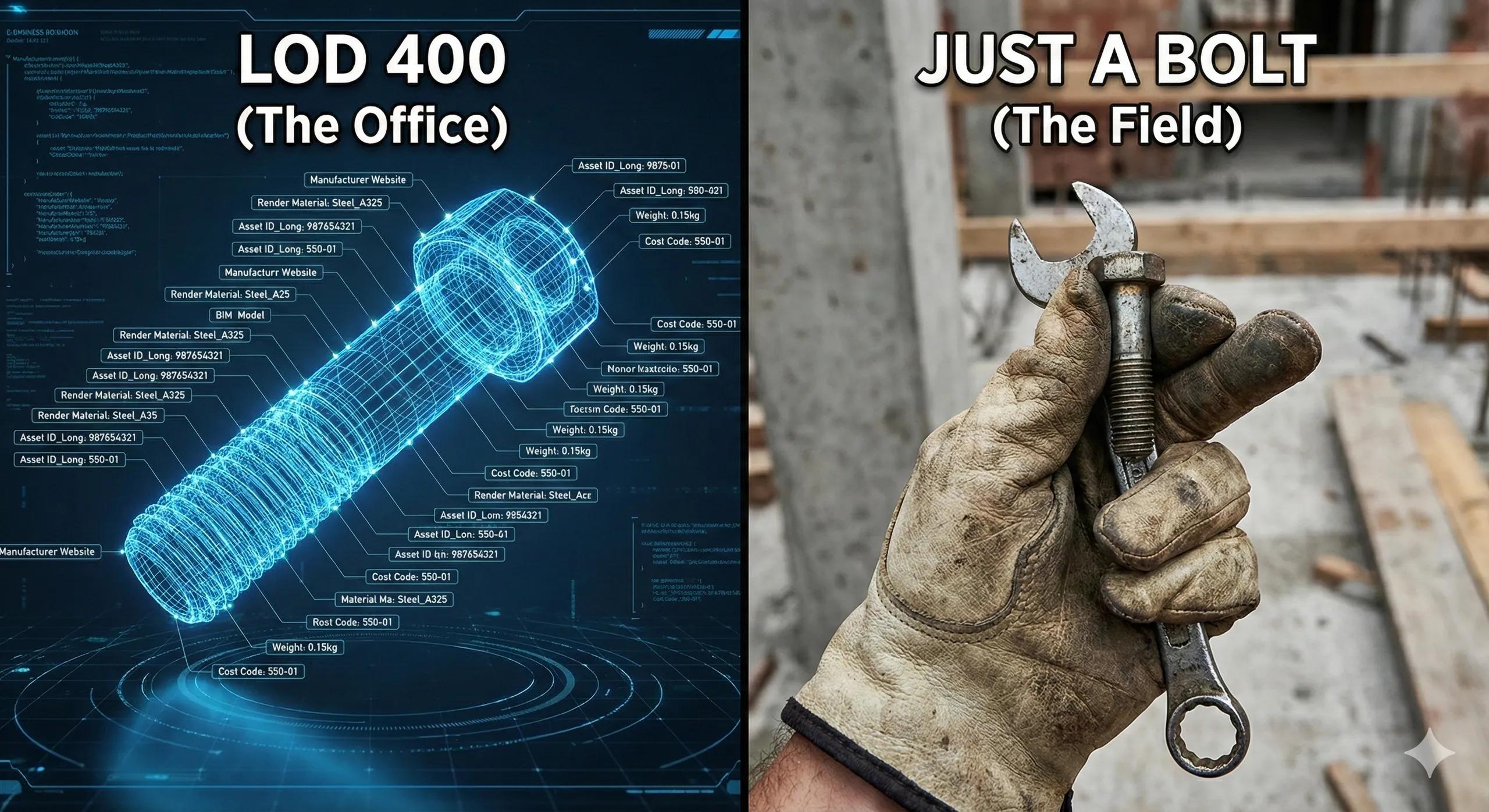
One of the most misunderstood concepts in BIM-to-field workflows is Level of Development (LOD) .
On paper, LOD appears simple: a numeric progression from conceptual geometry to as-built reality. In practice, LOD is often misused, over-applied, or misunderstood, especially when models leave the design office and enter the construction site.
Field teams rarely ask, “Is this model LOD 300 or 400?”
They ask, “Can I install this correctly with the information provided?”
This gap between what is modeled and what is constructible is where many BIM-to-field failures originate. This article clarifies what LOD truly means, how it should be defined for field execution, and how to avoid costly over-modeling and under-modeling.
1. LOD Is Not About Detail, It’s About Reliability
The most common misconception is equating LOD with visual detail.
More detail ≠ more useful
More geometry ≠ better constructability
LOD is fundamentally about confidence :
At this stage, can this information be relied upon for a specific purpose?
A model at LOD 300 may look detailed but still be unsafe for fabrication.
A model at LOD 400 may be geometrically rich but useless if metadata is missing.
For field teams, reliability beats visual richness every time .
2. Understanding the LOD Spectrum, Through a Field Lens
Let’s reinterpret LOD levels from the field’s point of view.
LOD 100, Conceptual
Massing models
Area-based volumes
No dimensional accuracy
Field relevance: None
Used only for feasibility and early planning.
LOD 200, Approximate Geometry
General system layouts
Indicative sizes and locations
Still flexible
Field relevance: Very limited
Cannot be used for layout, coordination, or installation.
LOD 300, Coordinated Design Geometry
Accurate size, shape, and location
Coordination-ready geometry
Discipline-level alignment
Field relevance:
✔ Suitable for coordination
✖ Not suitable for fabrication or installation
LOD 300 is often mistaken as “site-ready.” It is not.
LOD 350, Interface-Level Detail
Clear system interfaces
Defined connections
Clash-free junctions
Field relevance:
✔ Essential for coordination-driven construction
✔ Useful for prefabrication planning
This is where BIM begins to support construction logic.
LOD 400, Fabrication-Level Detail
Fabricator-specific geometry
Shop-drawing equivalent
Installation tolerances defined
Field relevance:
✔ Required for prefabrication
✔ Required for MEP installation
✔ Required for structural steel and modular components
LOD 400 is where BIM truly becomes constructible .
LOD 500, Verified As-Built
Field-validated geometry
Asset metadata complete
Matches reality
Field relevance:
✔ Required for handover
✔ Required for operations
✔ Required for digital twins
LOD 500 is not “modeled”, it is measured and verified .
3. The Real Problem: One LOD Does Not Fit All
A major BEP mistake is assigning a single LOD level across the entire model .
In reality:
Structural columns may need LOD 400
Architectural finishes may stay at LOD 300
Temporary works may need only LOD 200
Underground utilities may require LOD 350 + scan verification
Field success depends on LOD-by-element , not LOD-by-project.
4. Geometry vs Semantics: The Forgotten Half of LOD
Most teams focus only on geometric LOD. Field teams suffer because of semantic LOD gaps .
Geometric LOD answers
Where is it?
What shape is it?
How big is it?
Semantic LOD answers
What is it made of?
Who installs it?
What tolerance applies?
What asset ID does it have?
What maintenance regime applies?
A pipe modeled at LOD 400 with missing parameters is still unusable in the field.
Field teams need:
Installation codes
Material specs
Weight
Clearances
Access requirements
LOD must evolve both geometrically and semantically .
5. Aligning LOD With Construction Phases
Effective BIM-to-field workflows define LOD by construction intent , not design milestones.
Design Phase
LOD 200–300
Focus: coordination, planning, approvals
Pre-Construction
LOD 350–400 (selective)
Focus: interfaces, constructability, sequencing
Construction
LOD 400 (critical systems)
Reality capture validates installation
Handover
LOD 500
Verified using scans, surveys, and inspections
This phased LOD strategy prevents unnecessary modeling effort while ensuring field readiness.
6. LOD and Reality Capture: Closing the Loop
LOD 500 cannot be achieved through modeling alone.
It requires:
Drone surveys
Terrestrial laser scanning
GNSS-based validation
Deviation analysis
Only when the model matches measured reality does it reach LOD 500.
This is where BIM-to-field workflows transition into digital twin pipelines .
7. Common LOD Mistakes That Hurt the Field
Modeling everything to LOD 400 “just in case”
Ignoring semantic completeness
Treating LOD 300 as installation-ready
No differentiation between temporary and permanent works
No scan-based verification before claiming LOD 500
Each mistake adds cost without adding value.
8. What the Field Actually Needs From LOD
Field teams don’t need:
Over-detailed furniture
Perfect textures
Decorative modeling
They need:
Accurate coordinates
Verified clearances
Interface clarity
Installation logic
Trustworthy data
LOD should answer field questions, not impress reviewers.
Conclusion
Level of Development is not a modeling target, it is a commitment of reliability .
When LOD is defined correctly:
Designers model with intent
Contractors build with confidence
Rework reduces
Prefabrication succeeds
Digital twins emerge naturally
For BIM-to-field workflows to succeed, LOD must be:
Element-specific
Phase-aligned
Semantically complete
Verified against reality
Only then does BIM stop being a drawing tool and start becoming construction intelligence.